![]()
|
|
|
Build your own Voltage Controlled Relay (VCR)
Input select 0-5VDC, 0-10VDC or 0-XVDC (OEM), 4-20mA, 0-20mA; Where XVC custom input voltage see example B for 0-30VDC.
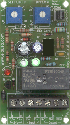
Input level trip set point multi-turn trimmer adjustment (via P1). Differential set point multi-turn trimmer adjustment (Via P2). Set Input select to 0-10V LED, relay on indicator.
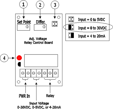
1. Input level set point multi-turn trimmer adjustment (via P1). 2. Differential set point multi-turn trimmer adjustment (Via P2). 3. Input select: 0-5VDC, 0-10VDC, 4-20mA 4. LED, relay on indicator.
Example A:
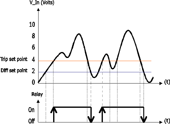
Control electric motor via the relay with input voltage greater then 4VDC. When the input voltage drop below 2VDC (equal to 50% of 4VDC trip point) turn off the relay therefore the motor.
* Set Input select to 0-10V
* Set Input trip level: Adjust the trip set point multi-turn trimmer adjustment (via P1) to 4VDC. Measured between ground to test point 1 (TP1).
* Set Input Cut out level: Adjust the differential set point multi-turn trimmer adjustment (Via P2) to 2VDC. Measured between ground to test point 2 (TP2).
Mount, connect wires and you done.
|
|
Example B:
Monitor 24V battery
1. Input level set point multi-turn trimmer adjustment (via P1). 2. Differential set point multi-turn trimmer adjustment (Via P2). 3. Input select: 0-5VDC, 0-30VDC (OEM custom board), 4-20mA 4. LED, relay on indicator.
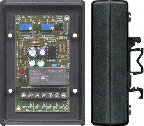
* Set Input select to 0-30V (As shown with OEM board modify to input of 0 to 30VDC). Please be advised that Enclosure, Din-Rail mount and mounting screws and Multi-turn trimmers options are sold separately.
* Set Input trip level: Adjust the trip set point multi-turn trimmer adjustment (via P1)
* Set Input Cut out level: Adjust the differential set point multi-turn trimmer adjustment (Via P2)
Mount via DIN-RAIL (option), connect wires, and you done.
|
|
|