![]()
|
|
||||||||||||||||||||
|
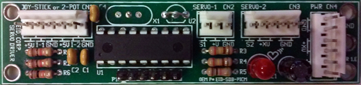
Industrial Joystick Controlled Dual RC Servo Motor Driver Interface Board Module is an Original Manufacturing Engineering (OEM) industrial and commercial rated high performance, high efficiency board that utilizes dual potentiometers (POT) center-type Joystick to control and drive both, RC Servos, direction, and angle.
Utilized miniature resistive joysticks (optional) to control dual servo motors-- Typical applications include CCTV (pan and tilt), robotics, electric wheelchairs, go-cart and measurement systems.
The Joystick Controlled Dual RC Servo Motors Driver & Control Interface Board Module power of 4 to 6VDC. An additional power input allows injection of higher voltage to RC SERVO 2 output, i.e. 7.4VDC, 12VDC etc.
The Joystick RC-Servo Motor Driver & Control Interface Board Module produces the required PWM multiplexing signals at 50 Hz of PWM main frequency (period of 20ms) for controlling the RC Servo motors. The PWM joystick is used for controlling the motors positions or directions. The positions and directions are direct result of the joystick's potentiometers (POTs, Pots) positions. The joystick driver board is designed to support both, Industrial high quality RC Servo motors that require 2000 levels corresponding to 0-5VDC POT’s position and/or 255 levels standard of low quality RC Servo motors.
Please be advised that the exact PWM width is depending on the servo motor types and brands. Let our OEM engineer’s custom “tailor” the Servo Motor Driver to meet your application requirements and needs.
Few models are available utilizing different micro processors. Remote dual potentiometers joystic connected via via wires and conveniently front mounted locking connectors.
The board also contains indication LED for Power On (PWR ON) and Microcontroller Self Testing (MST). The LED will blink "like HEART BEAT" once every second, indicating all of the board functions are running and powered correctly.
Shown above control remotely via external wired X/Y Joystick potentiometers Model J2
The board offers the features needed for professional setting Radio Control (RC) servo motors position as a direct function of joystick's potentiometer movement.
Mounting is easy via four 0.156" mounting holes using 6-32 screws and wire (optional) via convenient conventional industrial standards locking connectors.
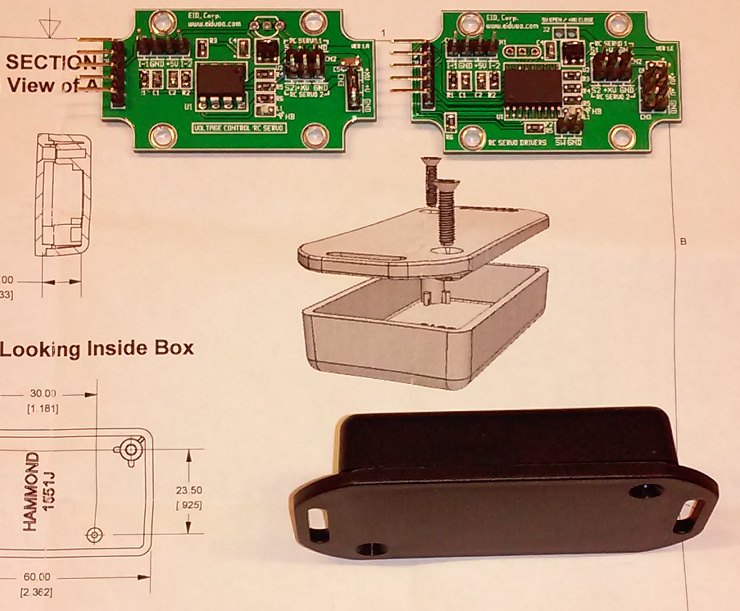
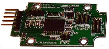
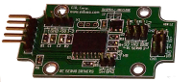
Let our OEM engineer designed one for your application-- Shown below an OEM versions for different customers. The boards below designed to fit in 1551J enclosure.
Shown above OEM board with Surface-mount technology (SMT) configuration, Model S2
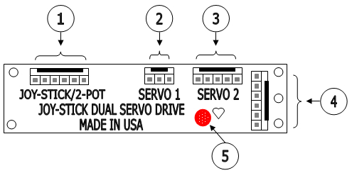
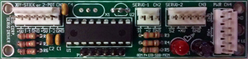
Shown above Joy-stick (or two potentiometers) controlled dual RC Servo Motor Driver Interface Board Module basic connections illustration
1. External Joystick dual channels, main potentiometers (POT-1 and POT-2) via locking type connector. Where; pins are marked (front left to right) +5V, Joystick potentiometer 1 Center-tap (I -1), +5V, Joystick potentiometer 2 Center-tap (I -2)
2. First channel external RC-Servo locking type connector. Where; pins are marked (front left to right) Signal (S-1), +V, GND
3. Second channel external RC-Servo locking type connector. Where; pins are marked (front left to right) Signal (S-2), +VX, +VX, GND, GND
4. External Power connections via locking type connector. Where; pins are marked (front top to bottom) GND, GND +VX, +VX, +V, +V
5. Heart-Beat LED indication.
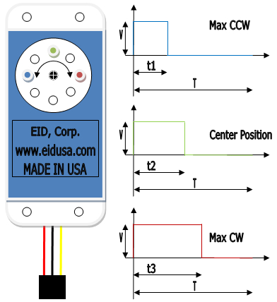
Illustration: RC Servo basic operation
Shown above RC Servo Motor basic operation illustration
Where;
T= 20.000mSec, t1= 1.000mSec, t2= 1.500mSec & t2= 2.000mSec, V = 4.8V to 24VDC (RC servo motor depended) & 3 wires: Red = Power, Black = Ground & Yellow = RC servo PWM signal.
Standard Features:
● Provides motors with smooth movement
● Linear Adjustable via Dual POTs Joystick
● High efficiency circuitry
● Conveniently front mounted connections
● Conveniently front mounted LED for both power on and Microcontroller Self Testing (MST) indicators.
Board Dimensions:
Board width, length, height: 3.45" * 0.825" * 0.5"
Board Mouthing Dimensions:
Four (4) mounting holes (.156" Dia.) 3.20" * 0.575" on center.
Note: Use four (4) 6-32 screws and stand-offs to mount the board.
Caution: Do not mount the board where ambient temperature is outside the range of -10° C (15° F) to 45° (115° F). -20°C to +50°C (-4°F to 122°F).
Specifications:
|
||||||||||||||||||||
|
||||||||||||||||||||
|
|
||||||||||||||||||||