![]()
|
|
|||||||||||||||||||||||||||||||||||||||||||||||||||||||||||||||||
|
Industrial DC Motor Control Interface Board Module is an Original Manufacturing Engineering (OEM) industrial and commercial rated high performance, high efficiency function add to an exiting speed control driver.
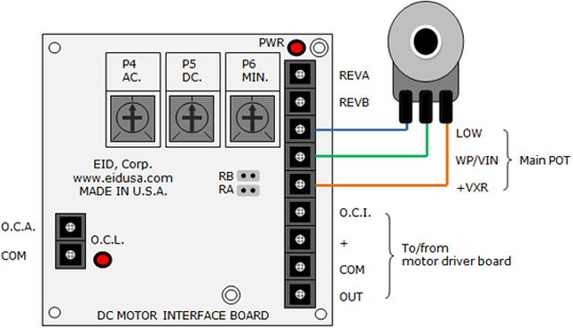
The DC Motor Control Interface Board power of 10VDC or 12VD from your exiting Motor control board or external power source. When 0 to 10VDC or 0 - 12VDC present in the input from external controller the linear acceleration and deceleration function will determine the ramp-up ramp-down time that the output signal reach this particular voltage. For some motor drive this signal is set via main speed Potentiometer (POT), the board can accommodate it with additional function of minimum setting for the external POT.
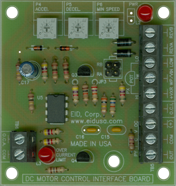
The board also contains induction LEDs for Power On (PWR ON) and Current Limit (CL).
Shown above left, adjustments via single turn trimmers (trimpot) and on the right with multi-turn trimmers (MTT for high accuracy
Shown above DC Motor universal interface board basic connections illustration
Board basic functions:
Acceleration (ACCEL) Sets the amount of time (0.1 to 12 Sec.) for the motor to accelerate from zero speed to full speed. It is equivalent to 0 to 10VDC that represent the full speed.
Motor Acceleration Start: The board contains an adjustable acceleration start feature which allows the motor to smoothly accelerate from zero speed to full speed over a time period of 0.1 to about 12 seconds. Acceleration Trimpot (ACCEL): The ACCEL Trimpot is provided to allow for a smooth start over an adjustable time period each time the AC power is applied or the Main Speed Potentiometer (MSP) is adjusted to a higher speed. The acceleration Trimpot (ACCEL) is factory set for 6 seconds. That is the amount of time it will take for the motor to accelerate from zero speed to full speed. To increase the acceleration time, rotate the ACCEL Trimpot clockwise. To decrease the acceleration time, rotate the ACCEL Trimpot counterclockwise.
Deceleration (DECEL), Sets the amount of time for the motor to decelerate from full speed to zero speed. It is equivalent to 10 to 0VDC that represent the minimum/zero speed.
Deceleration Trimpot (DECEL): The DECEL Trimpot controls the amount of ramp-down time when the Main Speed Potentiometer is adjusted to a lower speed. The DECEL Trimpot is factory set to 6 seconds, that is the amount of time it will take for the motor to decelerate from full speed to zero speed. To increase the deceleration time, rotate the DECEL Trimpot clockwise. To decrease the deceleration time, rotate the DECEL Trimpot counterclockwise. The DECEL Trimpot range is 0.1 to about 12 seconds. Please be advised that if the DECEL Trimpot is set to greater than the natural coast time of the motor and actual load, it will extend the deceleration time of the motor
Minimum (MIN.) Sets the minimum speed of the motor. Usually set between 0 to 5VDC. Minimum Speed Trimpot (MIN): The MIN Trimpot sets the minimum speed of the motor when the Main Speed Potentiometer is set fully counterclockwise. The MIN Trimpot is factory set to 0% of base motor speed. To increase the minimum speed, rotate the MIN Trimpot clockwise. To decrease the minimum speed, rotate the MIN Trimpot counterclockwise. The MIN Trimpot range is 0% to about 30% of base motor speed.
Please be advised, depending on driver from different manufactures some motor speed control the MIN Trimpot will affect the maximum speed setting. Therefore, it is necessary to readjust the MAX Trimpot if readjusting the MIN Trimpot. It may be necessary to repeat these adjustments until both the minimum and maximum speeds are set to the desired levels.
Indications/Diagnostic LEDs for both power On (PWR) and Current Limit (CL) signal.
Current Limit LED (CL): Will light and set open collector transistor to drive relay via terminal block. The CL Trimpot (not on board) is used to limit the maximum current (torque) to the motor. The CL also protects the control from excessive current during startup. The CL Trimpot usually (manufacture depended) is set to 150% of the full load current rating of the motor. To increase the current limit, rotate the CL Trimpot clockwise (do not exceed 150% of the full load current rating of the motor (maximum clockwise position)). To decrease the current limit, rotate the CL Trimpot counterclockwise. On cyclical loads, it may be normal for the CL LED to momentarily flash. (Visible only if the cover is removed.) The CL Trimpot range is 0% – 150% of the full load current rating of the motor. Some application may require a lower value so as not to damage process material or drive train components.
The board offers the features needed for professional ramping up or down your DC motor control.
Mounting is easy via four 0.125" mounting holes using 4-40 screws and wire (optional) via convenient conventional industrial standards Terminal Blocks (TB).
Standard Features:
● Provides motor with smooth variable speed
● Linear Adjustable Deceleration
● Linear Adjustable Acceleration
● Adjustable Minimum (MIN) speed,
● High efficiency circuitry.
● Conveniently front mounted terminal blocks.
● Conveniently front mounted LED for both power on and over current indicators.
Board Dimensions:
Board width, length, height: 2.45" * 2.45" * 0.75".
Board Mouthing Dimensions:
Four (4) mounting holes (.125" Dia.) 2.100" * 2.100" on center.
Note: Use four (4) 4-40 screws and stand-offs to mount the board.
Caution: Do not mount the board where ambient temperature is outside the range of -10° C (15° F) to 45° (115° F). -20°C to +50°C (-4°F to 122°F).
Specifications:
Model and Part Number (P#) Selection:
Board only
|
|||||||||||||||||||||||||||||||||||||||||||||||||||||||||||||||||
|
|||||||||||||||||||||||||||||||||||||||||||||||||||||||||||||||||
|
|
|||||||||||||||||||||||||||||||||||||||||||||||||||||||||||||||||